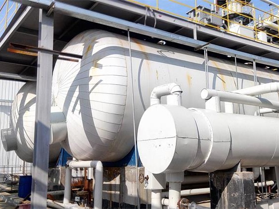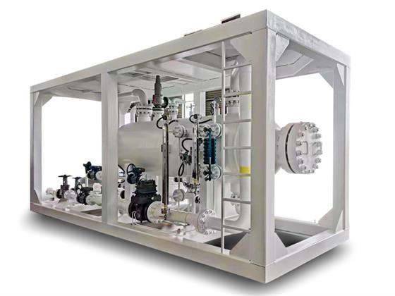
The three-phase separation of oil/gas/water is used for the separation and treatment of the products produced from oil wells or gas wells.
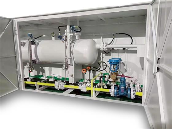
The three-phase separation of oil/gas/water is used for the separation and treatment of the products produced from oil wells or gas wells. The function of the separator is to separate the oil, gas and water into the corresponding oil-gas-water pipeline path, so as to enter the next process.
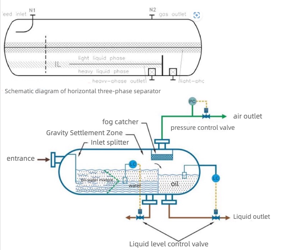
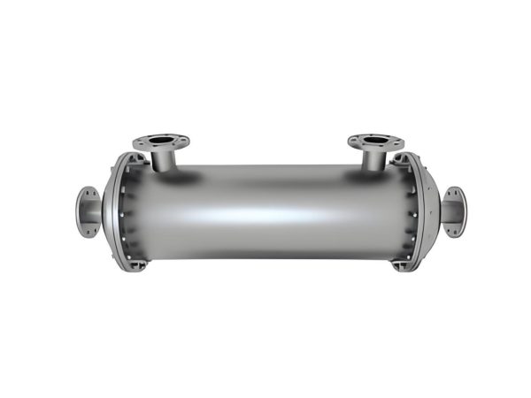
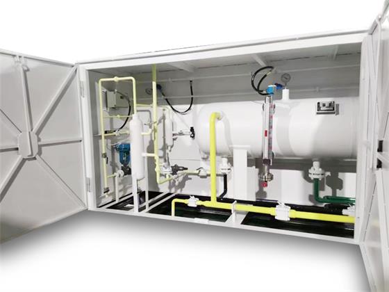
Compared with the two-phase separator, the three-phase separator has a complex structure. According to the flow rate of the processing medium, the separators are designed with different heights of baffles (weirs). The baffle plate is installed at the end of the separator. During the oil-water separation process, the medium flows from the inlet of the separator to the end. Due to the different density of the medium, the oil is separated from the oil outlet pipe at the upper end of the container through the precipitation separation of the internal structure, and the water is separated from the container. The lower water outlet flows away, thus completing the liquid separation operation.
horizontal separator/vertical separator
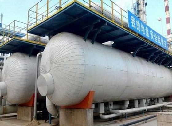
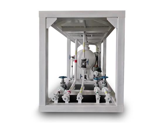
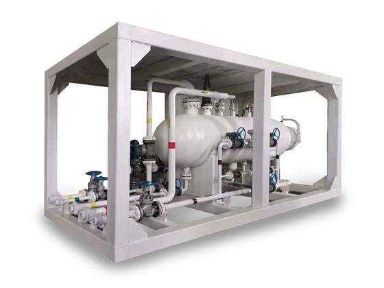
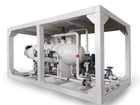
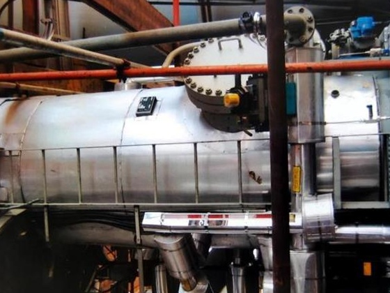
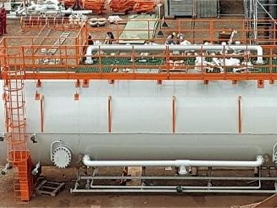
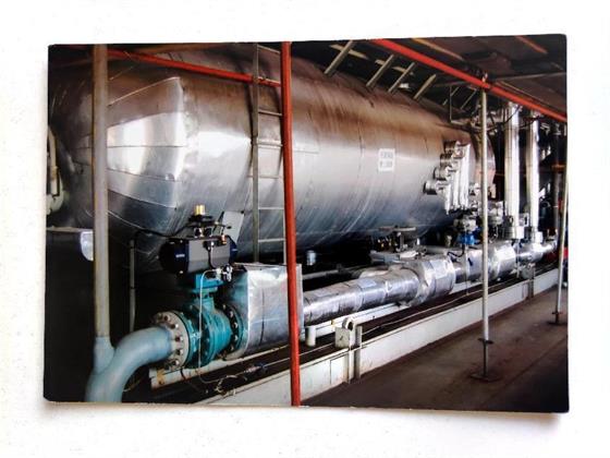
The horizontal separator is placed horizontally. The internal flow cross-sectional area of the horizontal separator is large, which prolongs the circulation time of the medium in the container, so as to achieve a better separation effect. Its advantages are stable structure and convenient operation.
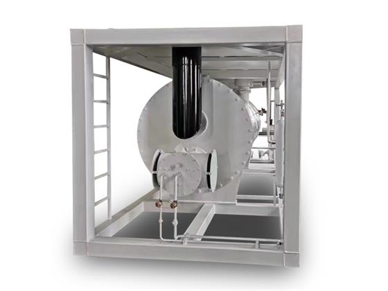
The vertical separator is installed vertically with the ground and can only be customized for special occasions where space is limited.
Test Separator, Production Separator, Two Phase Separator (Oil Water Separator), Three Phase Separator (Oil Gas Water Separator)
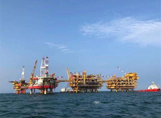
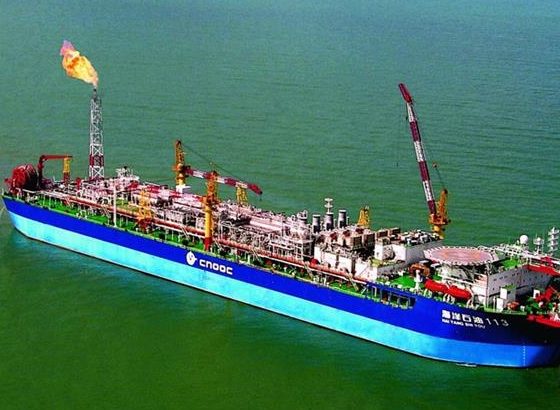
Mainly used in petroleum, petrochemical, natural gas oil-water separation and other industries.
| size | pressure | Entrance | oil export | water outlet | air outlet | operating temperature | Gas throughput | Liquid handling capacity | medium |
| 3000x900mm | 1.7Mpa | DN50 | DN50 | DN50 | DN100 | Max 90°C | 1-1 million cubic meters | 500-30000 thin/day | Oil and gas water |
| 3000x900mm | 3.5Mpa | DN100 | DN50 | DN50 | DN100 | ||||
| 3000x900mm | 10Mpa | DN100 | DN50 | DN50 | DN100 | ||||
| 3000x1200mm | 0.9Mpa | DN200 | DN80 | DN80 | DN200 | ||||
| 3000x1200mm | 1.7Mpa | DN150 | DN80 | DN80 | DN150 | ||||
| 3000x1200mm | 3.5Mpa | DN150 | DN80 | DN80 | DN150 | ||||
| 4500x1200mm | 0.9Mpa | DN200 | DN80 | DN80 | DN200 | ||||
| 4500x1200mm | 3.5Mpa | DN150 | DN80 | DN80 | DN150 | ||||
| 4500x1200mm | 10Mpa | DN150 | DN50 | DN50 | DN150 | ||||
| 5000x1200mm | 1.7Mpa | DN150 | DN80 | DN80 | DN150 | ||||
| 6000x1200mm | 2.0Mpa | DN200 | DN80 | DN80 | DN200 | ||||
| 4500x1800mm | 0.9Mpa | DN200 | DN80 | DN80 | DN200 | ||||
| 4500x1800mm | 1.7Mpa | DN200 | DN80 | DN80 | DN200 | ||||
| 4500x1800mm | 3.5Mpa | DN150 | DN80 | DN80 | DN150 | ||||
| 4500x1800mm | 1.7Mpa | DN200 | DN80 | DN80 | DN200 |